Pipelining Basics in Computer Architecture: Clock Cycle, Speedup and Hazard Worked Examples
Learn how to calculate a pipeline clock, fill and drain time, finite-batch speedup, latency, throughput, and the cost of a load-use stall.
KnowledgeGate Team
Exam prep & CS education
Updated 23 Oct 20266 min read
Pipelining can make one instruction slower while a stream finishes sooner. That is latency versus throughput. The clock follows the slowest stage plus register overhead, finite batches pay fill and drain time, and a load-use dependence can insert a stall. The GATE CS Exam Preparation Courses & Test Series page places these calculations in the broader syllabus.
Pipelining basics: overlap work without shortening the work itself
An instruction pipeline divides processing into stages that can work on different instructions during the same clock cycle. A standard teaching model uses IF -> ID -> EX -> MEM -> WB: instruction fetch, instruction decode, execute, memory access, and write back.
Keep four quantities separate:
Instruction latency is the time from an instruction entering the pipeline until it completes.
Throughput is the number of completed instructions per unit time.
Clock period is fixed by the slowest stage plus pipeline-register overhead.
Fill and drain are the startup and finishing cycles paid by a finite batch.
Pipelining in Computer Architecture Explained owns the equal-stage conceptual model. Pipelining in COA: Speedup, Hazards, and Worked GATE Examples owns broad efficiency and frequency-based CPI practice. Here the focus is finite-batch timing and a cycle-by-cycle load-use trace.
Pipelining timing formulas: derive them from the schedule
A k-stage pipeline accepts one new instruction per cycle when unstalled. The first instruction needs k cycles; each of the remaining n - 1 instructions adds one completion cycle:
base cycles = k + n - 1
If the stage logic delays are d_1, d_2, ..., d_k and every pipeline register adds overhead t_r, then:
T_clk = max(d_i) + t_r
T_pipe(n) = (k + n - 1)T_clk
For a stated non-pipelined reference that spends sum(d_i) on each instruction:
T_nonpipe(n) = n sum(d_i)
speedup = T_nonpipe(n) / T_pipe(n)
With s total stall cycles, use T_pipe(n) = (k + n - 1 + s)T_clk. This assumes one cycle per stage, one unstalled issue per cycle, and no unlisted cache or branch penalty.
Pipelining worked example: unequal stages, register overhead and 12 instructions
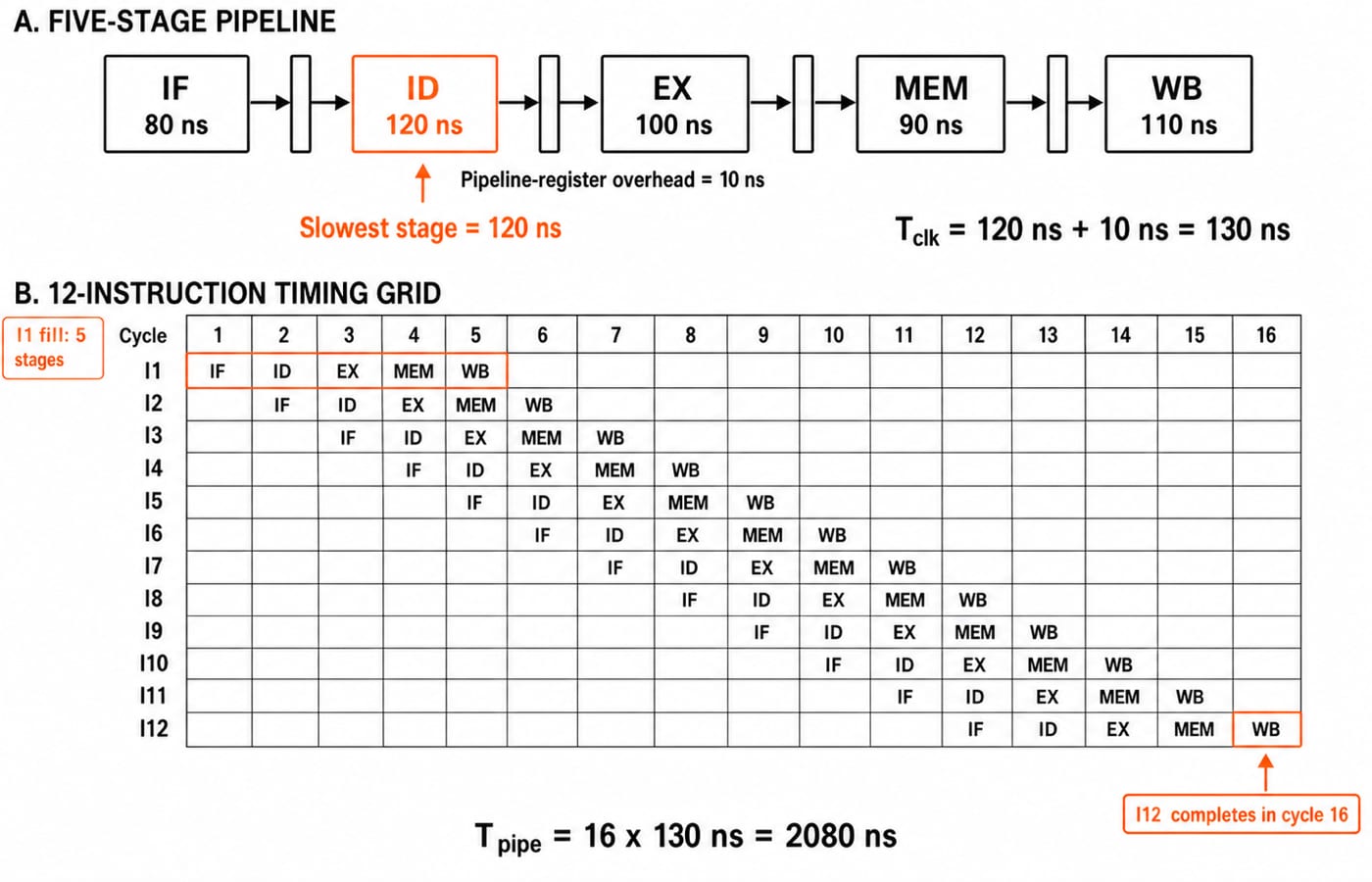
Consider a hypothetical five-stage datapath with logic delays 80 ns, 120 ns, 100 ns, 90 ns, 110 ns. Each interstage pipeline register adds 10 ns. The non-pipelined reference sends one instruction through the same logic in:
80 + 120 + 100 + 90 + 110 = 500 ns
For n = 12 independent instructions, the pipeline clock is:
T_clk = max(80, 120, 100, 90, 110) + 10 = 120 + 10 = 130 ns
The no-stall batch needs 5 + 12 - 1 = 16 cycles, so:
T_pipe = 16 x 130 = 2080 ns
The reference needs 12 x 500 = 6000 ns. Thus the finite-batch speedup is 6000 / 2080 = 2.8846, or 2.88x.
Now separate the other outputs. One instruction's no-stall pipeline latency is 5 x 130 = 650 ns. After filling, steady-state throughput is 1 / 130 ns, about 7.69 million instructions per second. Across this finite batch, average throughput is 12 / 2080 ns, about 5.77 million instructions per second.
The speedup is below five because the stages are unbalanced, registers add overhead, and a short batch pays fill and drain cost. Even as n becomes very large, the limit is 500 / 130 = 3.846x, not 5x.
Pipeline hazard worked example: one load-use stall with forwarding
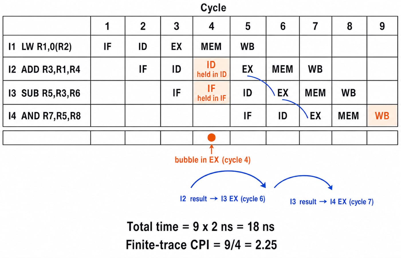
Use a five-stage IF-ID-EX-MEM-WB pipeline with full forwarding and a 2 ns clock. A load-use dependence needs one stall. Trace these instructions:
I1: LW  R1, 0(R2)
I2: ADD R3, R1, R4
I3: SUB R5, R3, R6
I4: AND R7, R5, R8
Instruction | 1 | 2 | 3 | 4 | 5 | 6 | 7 | 8 | 9 |
|---|---|---|---|---|---|---|---|---|---|
I1 | IF | ID | EX | MEM | WB | ||||
I2 | IF | ID | ID stall | EX | MEM | WB | |||
I3 | IF | IF stall | ID | EX | MEM | WB | |||
I4 | IF | ID | EX | MEM | WB | ||||
Bubble | EX |
Cycles 1 to 3 begin normally. In cycle 4, I1 is in MEM, I2 stays in ID, I3 stays in IF, and a bubble enters EX. In cycle 5, I1 reaches WB, while the other instructions advance. Forwarding supplies the ADD result to I3 in cycle 6 and the SUB result to I4 in cycle 7, so neither dependency adds a stall.
The no-stall base is 5 + 4 - 1 = 8 cycles. One stall makes 9 cycles, or 9 x 2 ns = 18 ns. The finite-trace CPI is 9 / 4 = 2.25. It includes fill, drain, and one bubble. It does not describe the steady-state CPI of every program.
Pipeline hazards: structural, data and control
Hazard | Why it occurs | What the pipeline must do | Example |
|---|---|---|---|
Structural | Two operations need one resource in the same cycle | Provide separate resources or stall |
|
Data | A consumer needs a value before its producer makes it available | Forward when timing permits, otherwise stall |
|
Control | A branch leaves the correct next PC uncertain | Resolve, predict, stall, or flush as the machine specifies | Fetched instructions follow the wrong branch path |
Trace RAW in this simple in-order model. WAR and WAW matter in designs that reorder operations or overlap writes.
Pipelining traps: the wrong shortcut and the correction
Wrong move | Why it fails | Correction |
|---|---|---|
Use the sum of stage delays as the pipeline clock | A cycle must fit the slowest stage, not all stages in sequence | Use |
Treat | That covers only the first instruction's no-stall latency | Use |
Forget the | The first instruction already occupies the first entry cycle | Here, |
Call higher throughput lower latency | Overlap can improve completion rate while one instruction takes longer | Pipeline latency is |
Add stall nanoseconds directly | Stalls are counted in whole clock cycles | Add stall cycles first, then multiply by |
Assume ideal speedup always equals | Unequal stages, register overhead, and finite batches reduce it | This five-stage design gives |
Use this scratch template: stage delays -> T_clk -> base cycles -> stalls -> total time -> reference time -> speedup. Calculate latency and throughput separately so they do not get mixed into the speedup.
How exams test pipelining: identify the requested quantity first
Common questions ask you to find the clock from stage delays and register overhead, calculate time or speedup for n instructions, distinguish latency from throughput, insert dependency bubbles, find asymptotic speedup, or determine the smallest batch that crosses a target speedup.
For the last pattern, find the minimum n that gives at least 3x speedup in our main example:
500n / [130(n + 4)] >= 3
500n >= 390n + 1560
110n >= 1560
n >= 14.1818
Therefore, the minimum whole number is 15. Check both sides of the boundary. At n = 14, speedup is 7000 / (18 x 130) = 7000 / 2340 = 2.991x. At n = 15, it is 7500 / (19 x 130) = 7500 / 2470 = 3.036x.
Keep this three-answer checkpoint: T_clk = 130 ns; the 12-instruction no-stall time is 2080 ns; the four-instruction hazard trace is 9 cycles, or 18 ns. The GATE Test Series is a route to timed practice after you can reproduce these steps.
Pipelining basics: the short version and next step
The slowest stage plus register overhead fixes the clock. Use k + n - 1 for no-stall cycles, add one cycle for every bubble, and keep latency separate from throughput. Speedup must use the explicitly stated reference machine.
Now reduce register overhead in the 12-instruction example from 10 ns to 5 ns: T_clk = 125 ns, pipeline time is 16 x 125 = 2000 ns, and speedup is 6000 / 2000 = 3x. Redraw both timing diagrams first. Then use GATE Guidance by Sanchit Sir for a wider structured GATE CS path.
Keep learning

Data Manipulation Micro-Operations in COA: Arithmetic, Logic and Shift Operations Worked Step by Step
Learn a fixed-width method for tracing arithmetic, logic, and shift micro-operations. Every example tracks register values, result bits, carry, and overflow.
Updated 19 Oct 20265 min readComputer Organization & Architecture
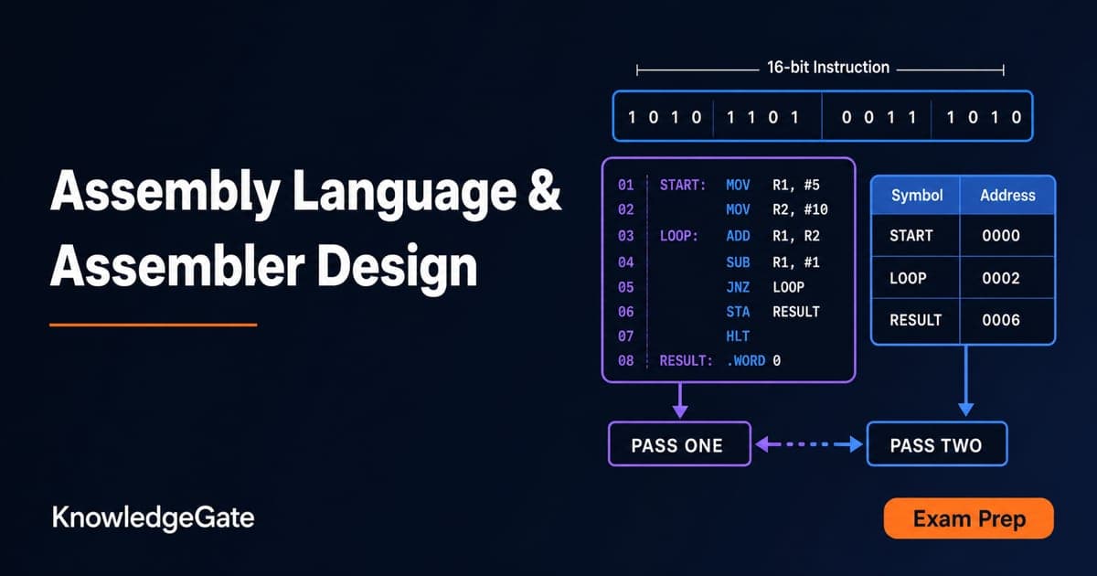
Assembly Language and Assembler Design: Two-Pass Translation with a Complete Worked Example
Follow a 16-bit Basic Computer program through pass one, pass two, hexadecimal encoding and execution, with every symbol, address and result shown.
Updated 15 Oct 20266 min readComputer Organization & Architecture

Computer Classification and Flynn’s Taxonomy: The Four Classes with a Worked Vector Example
A machine can belong to several computer classes at once. Learn the four classification axes, Flynn’s matrix, vector and multicore traces, and exam traps.
Updated 11 Oct 20266 min readComputer Organization & Architecture

Programmed I/O: Polling, CPU Utilisation, Worked Examples and GATE Question Patterns
Follow one programmed-input transfer from control write to data read, then calculate how many polls one word costs and what a longer poll period buys.
Updated 7 Oct 20266 min readComputer Organization & Architecture