Computer Interfaces in COA: Registers, Handshaking and I/O Mode Numericals
Learn how an I/O interface decodes addresses, uses data, status and control registers, coordinates handshakes, and changes CPU occupancy across polling, interrupts and DMA.
KnowledgeGate Team
Exam prep & CS education
Updated 30 Aug 20267 min read
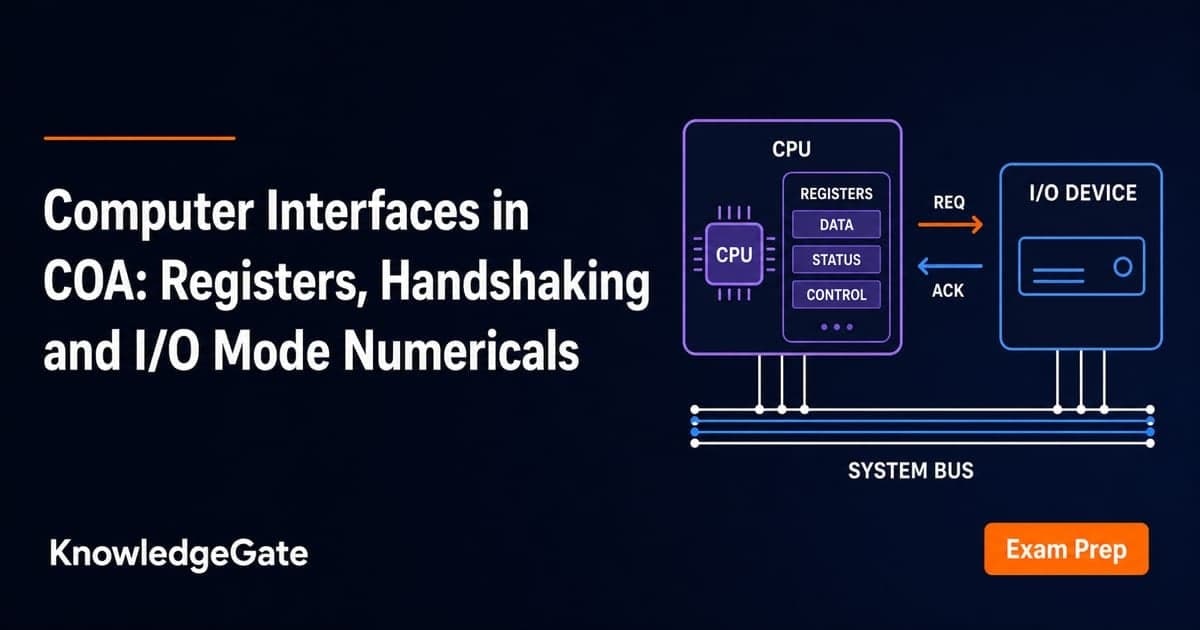
In COA, a computer interface is not a graphical screen or a software API. It is the hardware boundary that lets the processor exchange data and control signals with a peripheral. Terms such as data register, status register, polling, interrupts and DMA are easy to memorise separately, but questions make you trace their order or calculate CPU time. The safest method is to trace the register sequence first, then keep device elapsed time separate from CPU occupancy.
Computer interfaces in COA: the boundary between the bus and a device
A computer interface is the hardware and control boundary between the processor or system bus and a peripheral whose speed, data format and timing can differ from the CPU. The CPU supplies address, data and control signals; the interface decodes and buffers them; the device produces or consumes the data.
Its jobs include address decoding, temporary buffering, status reporting, command storage, timing conversion, error indication, and interrupt or DMA signalling. Without this boundary, directly connecting a fast synchronous processor to a variable-latency device would make ready states and timing ambiguous.
Three registers recur throughout the topic. A data register carries a byte or word, a status register reports ready, busy or error, and a control register stores start, reset, mode or interrupt-enable bits.
For the topic map above this level — how the three registers fit the whole I/O picture, what memory-mapped addressing costs the address space, and how interrupt priority is arbitrated — start from Input Output Organisation in COA. This post stays inside one transaction: exact register addresses, exact bit patterns, exact handshake timings.
Interface registers and I/O addressing: trace an exact transaction
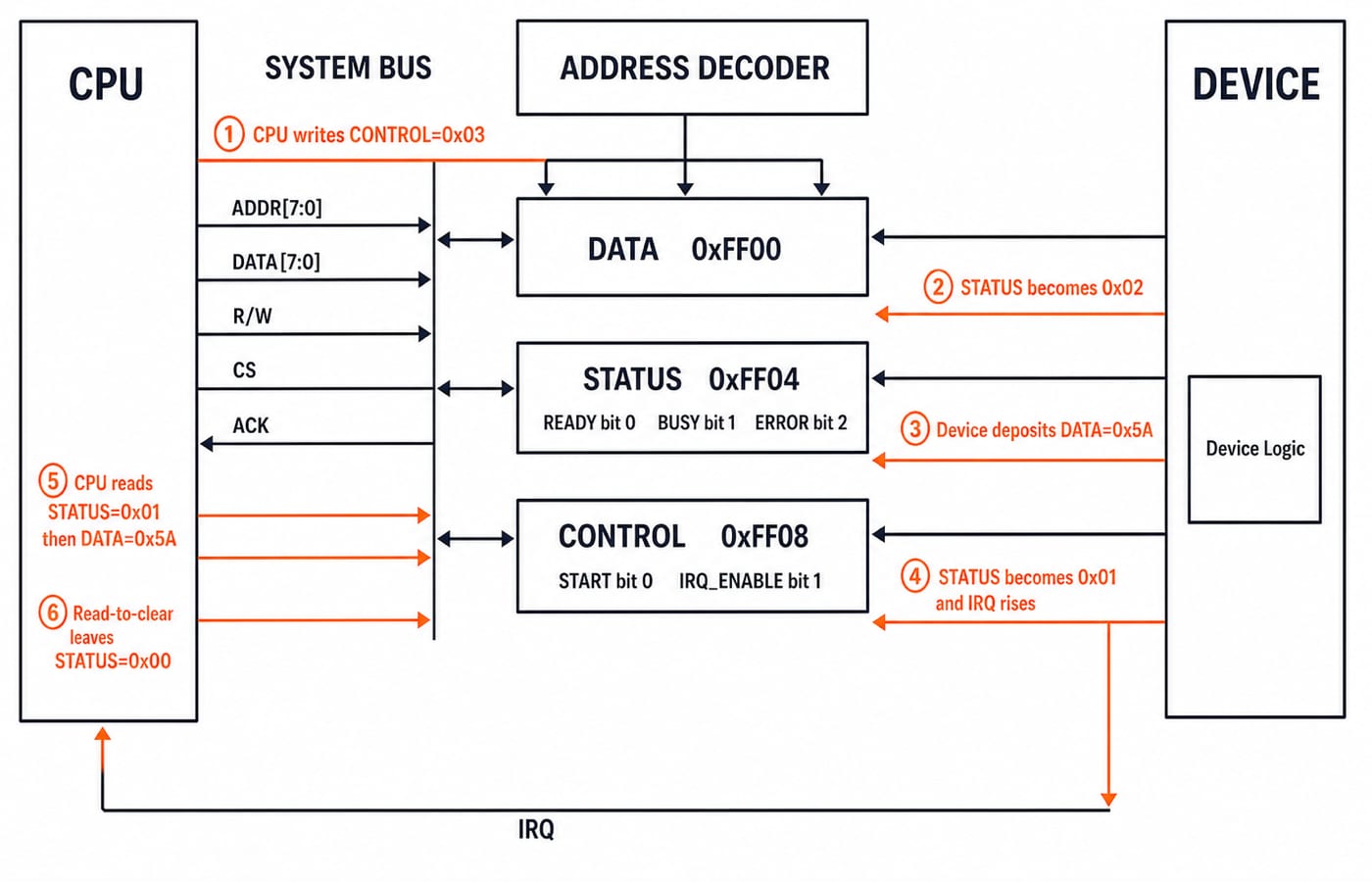
This hypothetical memory-mapped 8-bit input interface uses addresses and bit meanings defined only for this example.
Address | Register | Meaning |
|---|---|---|
|
| Holds the input byte |
|
| Bit 0 |
|
| Bit 0 |
The CPU writes 0x03 to CONTROL, setting START=1 and IRQ_ENABLE=1. While the device works, STATUS=0x02, so BUSY=1. When byte 0x6D arrives, the interface places it in DATA, sets STATUS=0x01, so READY=1, and raises the interrupt. The handler reads STATUS=0x01 to confirm readiness and then DATA=0x6D. This example's read-to-clear rule returns STATUS to 0x00.
Memory-mapped I/O shares the memory address space and uses normal load or store instructions. Isolated I/O uses a separate I/O space and dedicated instructions or control signals. Neither is inherently faster. Addressing Modes and Instruction Formats provides the wider instruction-encoding context.
Programmed I/O, interrupt-driven I/O and DMA at the interface: status, ISR or controller
At the interface boundary, the important distinction is how readiness reaches the CPU and whether CPU instructions or a DMA controller perform the memory transfer.
Mode | How readiness is noticed | Who moves data to or from memory | CPU involvement |
|---|---|---|---|
Programmed I/O | CPU polls status | CPU | Polling and transfer for every unit |
Interrupt-driven I/O | Interface interrupts | CPU through the ISR | Other work, then service per event |
DMA | DMA request and controller logic | DMA controller | Setup and completion handling |
An interrupt avoids continuous polling, but does not autonomously transfer a block. The ISR uses CPU instructions to move data. DMA reduces per-word CPU service, but still needs setup, bus arbitration and completion handling.
Polling can suit a tiny or immediately ready transfer, interrupts suit intermittent events, and DMA earns its setup cost on larger blocks. Device rate, buffer size, bus contention and service cost determine the actual result.
I/O mode worked numerical: CPU occupancy for an 8 MiB transfer
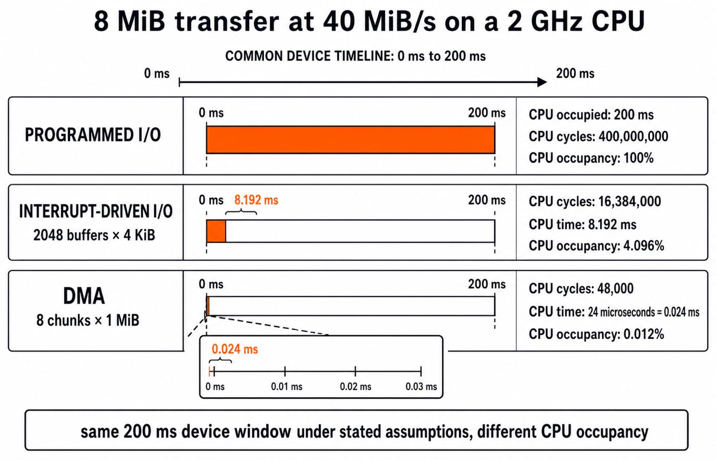
Assume an 8 MiB block streams at 40 MiB/s on a 2 GHz CPU. The interface and bus sustain that rate, bus contention is ignored, and programmed I/O polls throughout. Interrupt-driven I/O uses one interrupt per 4 KiB buffer at 8000 cycles, including copying and bookkeeping. DMA uses 1 MiB chunks at 6000 cycles for setup and completion.
The common device window is:
8 MiB / 40 MiB/s = 0.2 s = 200 ms
For programmed I/O, the CPU is busy throughout:
0.2 s × 2,000,000,000 cycles/s = 400,000,000 cycles
Busy time is 200 ms; occupancy is 200 / 200 × 100 = 100%.
For interrupts, first count the buffers:
8 MiB / 4 KiB = (8 × 1024 KiB) / 4 KiB = 2048 buffers
2048 × 8000 = 16,384,000 cycles
16,384,000 / 2,000,000,000 = 0.008192 s = 8.192 ms
Occupancy is 8.192 / 200 × 100 = 4.096%.
For DMA, 8 MiB / 1 MiB = 8 chunks.
8 × 6000 = 48,000 cycles
48,000 / 2,000,000,000 = 0.000024 s = 24 microseconds = 0.024 ms
Occupancy is 0.024 / 200 × 100 = 0.012%.
Result | Window | CPU cycles | CPU time | Occupancy |
|---|---|---|---|---|
Device transfer |
|
|
|
|
Programmed I/O |
|
|
|
|
Interrupt-driven I/O |
|
|
|
|
DMA |
|
|
|
|
All three have the same 200 ms device window under these assumptions. DMA frees CPU time; it does not raise the device's 40 MiB/s rate.
This table prices CPU occupancy from buffer and chunk granularity. For the complementary arithmetic — what fraction of a bus clock a DMA controller steals, and what fraction of a CPU a per-byte ISR consumes — work through DMA, Interrupts and Programmed I/O for GATE, which uses a bus-cycle accounting unit rather than a device window.
Asynchronous handshaking: a four-event transfer with real timing values
A synchronous transfer uses a shared timing reference. An asynchronous transfer cannot assume a fixed receiver delay, so a request-acknowledge handshake confirms data availability and acceptance.
For one 8-bit transfer:
Time | Event | State after the event |
|---|---|---|
| Interface places | Data= |
| Device latches | Data accepted, |
| Interface sees |
|
| Device sees |
|
If the next transfer begins at 170 ns, the ideal upper bound is 1 / 170 ns = 5.88 million transfers per second. At one byte per handshake, that is about 5.88 million bytes per second. This is a bound for the stated trace, not a measured specification.
Computer-interface traps: diagnose the wrong model before calculating
Most wrong answers begin with a wrong model, not difficult arithmetic.
Trap | What goes wrong | Correction |
|---|---|---|
Peripheral equals interface | Controller state and device behaviour mix | Interface is the register boundary; peripheral is the device |
Memory-mapped I/O means DMA | Addressing and transfer methods get coupled | Treat them as independent choices |
Interrupt moves a block | CPU service disappears from the model | An ISR runs on the CPU unless DMA transfers data |
MB mixed with MiB | Counts and times become inconsistent | Use |
Lower CPU time means shorter transfer | CPU occupancy and elapsed time get confused | Calculate device and CPU times separately |
Order matters too. Reading DATA before checking READY can consume stale or invalid data. Failing to acknowledge completion can leave an interrupt asserted. Tie clearing behaviour to the stated rule, such as this example's read-to-clear action, because controllers differ.
The addresses and percentages above are one worked teaching model; real hardware differs, and the skill is running the method on whatever map a question supplies.
How computer interfaces are tested: registers, event order and numericals
Exam questions commonly ask you to identify data, status and control-register roles; distinguish memory-mapped from isolated I/O; order polling or interrupt events; calculate buffers, interrupts, cycles or CPU occupancy; and choose programmed I/O, interrupts or DMA under stated assumptions.
Use the same solving order every time:
Write the transfer unit.
Convert the block size into those units.
Calculate device elapsed time.
Count CPU service events and cycles.
Convert cycles using the CPU frequency.
Compare like with like.
Keep the unit beside every intermediate value so bytes, words, buffers, seconds and cycles never mix. GATE CS Exam Preparation provides the broader subject route, while the GATE Test Series is an optional route for timed practice.
The short version and your next step
The interface decodes and buffers.
Data, status and control registers have different jobs.
Polling keeps checking.
Interrupts summon CPU service.
DMA moves blocks after setup.
In the worked model, the device window stays 200 ms, but CPU busy time falls from 200 ms to 8.192 ms to 0.024 ms. For a structured route through the wider subject, GATE Guidance by Sanchit Sir is an optional next step.
Keep learning
Pipelining Basics in Computer Architecture: Clock Cycle, Speedup and Hazard Worked Examples
Learn how to calculate a pipeline clock, fill and drain time, finite-batch speedup, latency, throughput, and the cost of a load-use stall.
Updated 23 Oct 20266 min readComputer Organization & Architecture
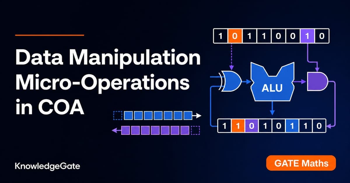
Data Manipulation Micro-Operations in COA: Arithmetic, Logic and Shift Operations Worked Step by Step
Learn a fixed-width method for tracing arithmetic, logic, and shift micro-operations. Every example tracks register values, result bits, carry, and overflow.
Updated 19 Oct 20265 min readComputer Organization & Architecture
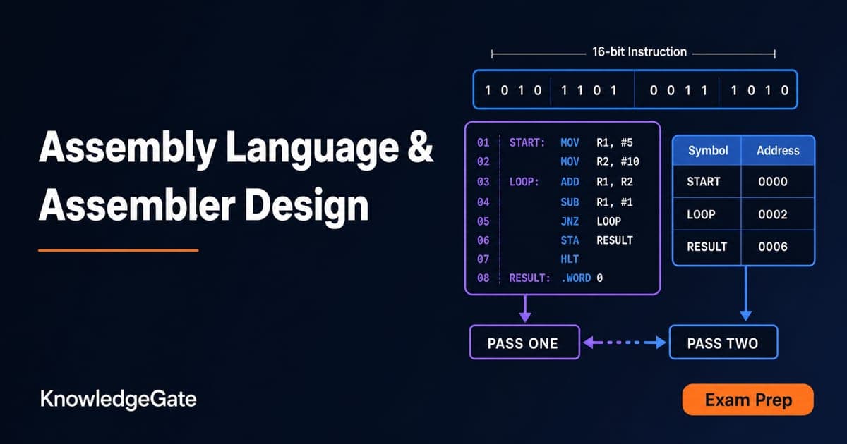
Assembly Language and Assembler Design: Two-Pass Translation with a Complete Worked Example
Follow a 16-bit Basic Computer program through pass one, pass two, hexadecimal encoding and execution, with every symbol, address and result shown.
Updated 15 Oct 20266 min readComputer Organization & Architecture
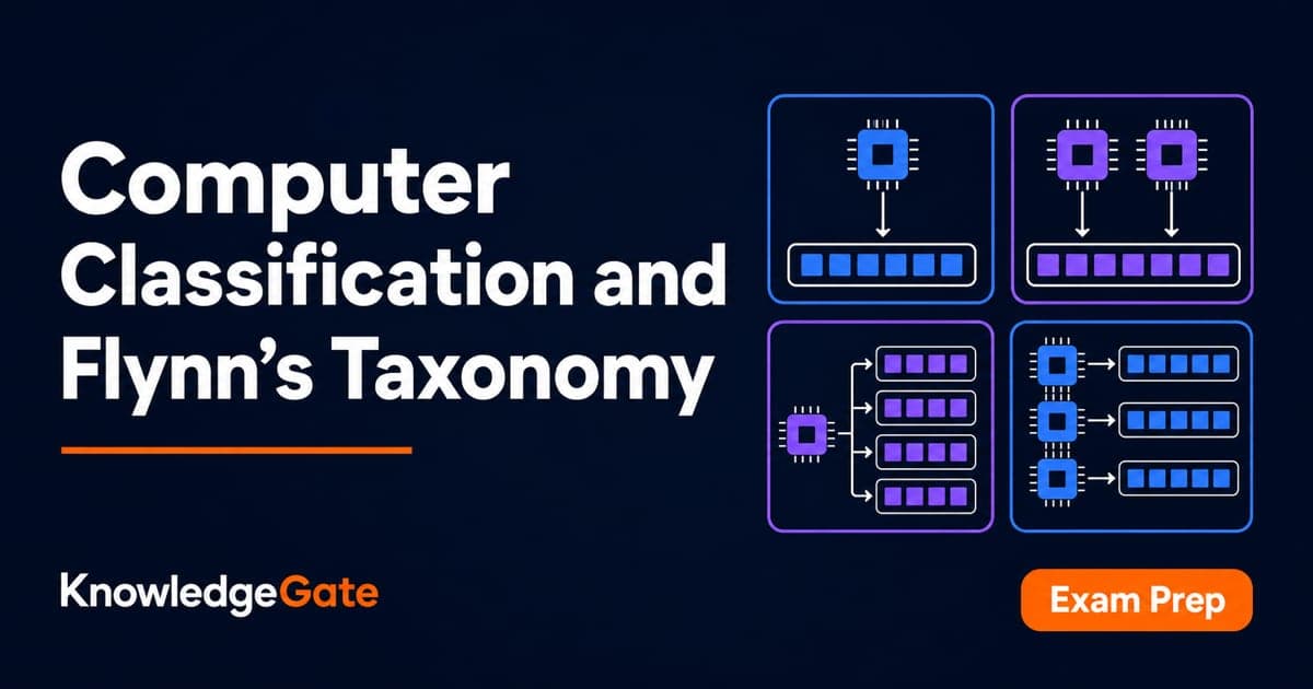
Computer Classification and Flynn’s Taxonomy: The Four Classes with a Worked Vector Example
A machine can belong to several computer classes at once. Learn the four classification axes, Flynn’s matrix, vector and multicore traces, and exam traps.
Updated 11 Oct 20266 min readComputer Organization & Architecture