Flip-Flop Conversion for GATE: Excitation Tables and the SR, JK, D, T Conversion Recipe, Solved
Convert one flip-flop into another with the target transition, the available device's excitation table and a K-map. The solved JK-to-T case shows every row.
KnowledgeGate Team
Exam prep & CS education
Updated 20 Jul 20266 min read97 views

"Convert a JK flip-flop to a T flip-flop" looks like a circuit-design problem with many possible tricks. It is actually the same four-step table procedure every time.
The hinge is the excitation table. Once you can move from a required state transition to the inputs of the available flip-flop, the remaining work is one K-map and a small wiring diagram.
Characteristic table vs excitation table
A characteristic table starts with the inputs and present state, then gives Q(next). An excitation table runs backwards: start with Q and the Q(next) you want, then find the inputs that produce that transition.
Conversion needs excitation. The target flip-flop supplies the transition, and the available flip-flop's excitation table supplies the inputs.
The symbol X means don't care. Either 0 or 1 works for that input in that row. Those X entries are not missing information. They let a K-map form larger groups and produce simpler input equations.
The four excitation tables you must know cold
SR excitation table
Q | Q(next) | S | R | Meaning |
|---|---|---|---|---|
0 | 0 | 0 | X | Keep 0 |
0 | 1 | 1 | 0 | Set |
1 | 0 | 0 | 1 | Reset |
1 | 1 | X | 0 | Keep 1 |
The SR combination S = 1, R = 1 is forbidden, so SR offers fewer useful don't-cares than JK.
JK excitation table
Q | Q(next) | J | K | Meaning |
|---|---|---|---|---|
0 | 0 | 0 | X | Keep 0 |
0 | 1 | 1 | X | Set |
1 | 0 | X | 1 | Reset |
1 | 1 | X | 0 | Keep 1 |
JK has no forbidden input. J = K = 1 toggles the state.
D excitation table
Q | Q(next) | D |
|---|---|---|
0 | 0 | 0 |
0 | 1 | 1 |
1 | 0 | 0 |
1 | 1 | 1 |
The rule is D = Q(next).
T excitation table
Q | Q(next) | T |
|---|---|---|
0 | 0 | 0 |
0 | 1 | 1 |
1 | 0 | 1 |
1 | 1 | 0 |
The rule is T = Q XOR Q(next). T = 0 holds and T = 1 toggles.
The same four tables also drive counter design, where the excitation lookup fills a state table instead of a conversion table. That treatment, with a worked 2-bit synchronous counter, is in Sequential circuits: flip-flops, latches and counters explained.
The conversion recipe in four steps
Suppose an available flip-flop must reproduce the behaviour of a target flip-flop.
Write columns for the target input or inputs, present state Q and the target's resulting Q(next).
For every row, read the required input values from the excitation table of the available flip-flop.
Make one K-map for each input of the available flip-flop, using the target input variables and Q.
Simplify the maps and connect the resulting equations to the available inputs.
Target behaviour produces Q(next). Available-device excitation produces the wiring equations.
Worked example: JK flip-flop converted to a T flip-flop
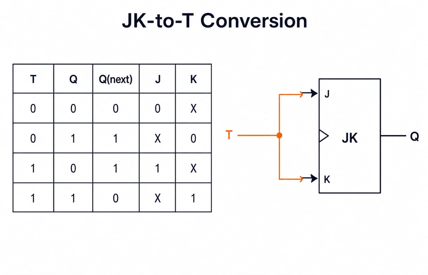
The available hardware is JK. The required external behaviour is T. A T flip-flop holds when T = 0 and toggles when T = 1, so:
Q(next) = Q XOR T
Now build all four combinations of T and Q, compute Q(next), and consult the JK excitation table.
T | Q | Q(next) | Required J | Required K |
|---|---|---|---|---|
0 | 0 | 0 | 0 | X |
0 | 1 | 1 | X | 0 |
1 | 0 | 1 | 1 | X |
1 | 1 | 0 | X | 1 |
Check the rows one at a time:
T = 0, Q = 0 gives Q(next) = 0. The transition 0 -> 0 needs J = 0, K = X.
T = 0, Q = 1 gives Q(next) = 1. The transition 1 -> 1 needs J = X, K = 0.
T = 1, Q = 0 gives Q(next) = 1. The transition 0 -> 1 needs J = 1, K = X.
T = 1, Q = 1 gives Q(next) = 0. The transition 1 -> 0 needs J = X, K = 1.
For J, the map has 0 at (T = 0, Q = 0), 1 at (T = 1, Q = 0), and X in both Q = 1 cells. Use the X at (1, 1) to group the T = 1 row:
J = T
For K, the map has X at both Q = 0 cells, 0 at (T = 0, Q = 1), and 1 at (T = 1, Q = 1). Again group the T = 1 row:
K = T
Tie J and K together and drive both with T. T = 0 makes JK hold, while T = 1 makes it toggle, exactly matching T behaviour.
SR flip-flop converted to D behaviour
SR is the one available device with a forbidden input, so it is worth working end to end. The target is D behaviour, Q(next) = D. Build the four combinations of D and Q, then read each required transition from the SR excitation table.
D | Q | Q(next) | Required S | Required R |
|---|---|---|---|---|
0 | 0 | 0 | 0 | X |
0 | 1 | 0 | 0 | 1 |
1 | 0 | 1 | 1 | 0 |
1 | 1 | 1 | X | 0 |
For S, the map has 0 at (D = 0, Q = 0), 0 at (D = 0, Q = 1), 1 at (D = 1, Q = 0) and X at (D = 1, Q = 1). Use that X to group the whole D = 1 column:
S = D
For R, the map has X at (D = 0, Q = 0), 1 at (D = 0, Q = 1) and 0 in both D = 1 cells. Use that X to group the whole D = 0 column:
R = NOT D
Feed D straight to S and its inverse to R. S and R can never both be 1, because that would need D to be 0 and 1 at the same time, so the forbidden combination is unreachable by construction rather than by checking afterwards.
Two conversions you should do in seconds
D flip-flop converted to T behaviour
The target T behaviour is Q(next) = Q XOR T. A D flip-flop always requires D = Q(next). Substitute the target equation:
D = Q XOR T
Feed Q and the external T input into an XOR gate, and connect its output to D.
T flip-flop converted to D behaviour
The target D behaviour is Q(next) = D, where D is the target's external input. The available T flip-flop requires T = Q XOR Q(next). Substitute Q(next) = D:
T = Q XOR D
These are mirror conversions. Both come directly from the D and T excitation rules, so a K-map would only reproduce the XOR equation.
Traps that flip the answer
Using a characteristic table for excitation
The characteristic table moves from inputs to next state, but conversion needs to move from required transition to available inputs. Write "available excitation" above the input columns before filling them.
Treating don't-cares as zeros
An X may be 0 or 1, whichever simplifies the map. Use it for larger groups, but never cover a required zero.
Forgetting the forbidden SR input
If SR is the available device, the final equations must never require S = R = 1 for a valid combination. Check all rows after simplification, not only the K-map groups.
Swapping available and target devices
In "JK to T", JK is available and T is the target behaviour. Use the T rule to compute Q(next), then use JK excitation to find J and K. Say that sentence before starting.
How GATE tests flip-flop conversion
GATE can ask for conversion equations, ask which flip-flop a shown circuit realises, or trace a next-state sequence. For a shown circuit, write its input equations, find Q(next) from the available device, then compare that result with SR, JK, D and T behaviour.
Digital Electronics coverage and its marks are set each cycle in the brochure on the official GATE portal of the organising IIT. Confirm the current-year subject list there rather than assuming that an older marks split still applies. The GATE category is useful for preparation material, but the official brochure controls the examination syllabus.
Short version and next step
The short version is: use the target flip-flop to calculate Q(next), use the available flip-flop's excitation table to find its inputs, then simplify each input with a K-map. Memorise all four excitation tables and the two XOR shortcuts, D = Q XOR T and T = Q XOR D for the corresponding conversions.
Practise the procedure through the GATE Guidance by Sanchit Sir course and the Sequential Circuits MCQ set. Digital Electronics carries about 1,500 practice questions across the learn modules, which is enough repetition to make the table procedure automatic.
Keep learning
NOT, OR and AND Gates: Evolution, Truth Tables and a Worked Circuit
Learn how NOT, OR and AND gates developed from switching ideas, then trace F=(A+B')C node by node and confirm it with a complete truth table.
Updated 23 Oct 20265 min readDigital Logic
Binary Arithmetic Operations Explained: Rules and Worked Examples
Learn binary addition, subtraction, multiplication and division with aligned worked examples, then separate carry, borrow and two's-complement overflow.
Updated 19 Oct 20266 min readDigital Logic

1's Complement Explained: Binary Conversion, Addition and Worked Examples
Learn how fixed-width 1's complement numbers represent negatives, why zero has two encodings, and how end-around carry works through exact examples.
Updated 15 Oct 20266 min readDigital Logic
Decimal Conversion Explained: Binary, Octal and Hexadecimal Worked Examples
Learn one dependable method for converting values between decimal, binary, octal and hexadecimal, including fractions, shortcuts and checks.
Updated 11 Oct 20265 min readDigital Logic