Flip-Flop Conversion Explained: Tables, K-Maps and a Worked D-to-JK Design
Learn a repeatable flip-flop conversion method, then derive and verify the combinational logic that makes a D flip-flop behave exactly like a JK flip-flop.
KnowledgeGate Team
Exam prep & CS education
Updated 25 Oct 20265 min read

Memorising four characteristic tables is manageable. A conversion question is harder because it mixes present state, required next state, excitation inputs and don't-cares in one table. The conversion method starts from desired JK behaviour, derives the input of an available D flip-flop, reaches D=JQ'+K'Q, and verifies it across six clock edges.
Fix the direction first: convert D to JK means using a D flip-flop with combinational logic so its external behaviour matches a JK flip-flop. The physical storage element remains D type.
1. Flip-flop conversion starts with present state and next state
A flip-flop is a one-bit, edge-triggered storage element. Write Q or Q(t) for the value before the active clock edge, and Q+ or Q(t+1) for the value captured after it. Inputs may settle between edges, but a conversion table compares state only across the stated active edge.
Keep these three tools separate:
A characteristic table maps flip-flop inputs and present
QtoQ+.An excitation table maps a required
Q -> Q+transition to input values that can cause it.A characteristic equation expresses the next state algebraically for simplification and checking.
The conversion equations describe synchronous behaviour. Asynchronous preset and clear override the clocked data path and sit outside the basic conversion equations. Review Sequential Circuits: Flip-Flops and Counters if you need the wider context.
2. SR, JK, D and T behaviour in one exact reference table
Type | Input condition |
| Meaning |
|---|---|---|---|
SR |
|
| hold |
SR |
|
| reset |
SR |
|
| set |
SR |
| invalid | forbidden in the standard active-high model |
JK |
|
| hold |
JK |
|
| reset |
JK |
|
| set |
JK |
|
| toggle |
D |
|
| store 0 |
D |
|
| store 1 |
T |
|
| hold |
T |
|
| toggle |
The corresponding characteristic equations are:
SR:
Q+=S+R'Q, with the valid-input restrictionSR != 11JK:
Q+=JQ'+K'QD:
Q+=DT:
Q+=T XOR Q=T'Q+TQ'
JK removes the SR forbidden input by making J=K=1 toggle. D removes ambiguity because its input equals the required next state. Use Flip-Flop Conversion for GATE: Excitation Tables and Conversion Recipe for excitation lookup through its JK-to-T and SR-to-D examples. For D-to-JK, the required D input is unique in all eight rows, and the resulting equation must survive the six-edge trace.
3. The four-step conversion method, with direction fixed first
Identify the desired flip-flop and the available flip-flop.
List every desired input combination with present
Q.Compute desired
Q+from the desired flip-flop.Use the available flip-flop's excitation requirement to fill its inputs, then minimise each available input as a function of desired inputs and
Q.
Here JK is desired and D is available. Thus J, K and current Q are table variables, while D is derived. Since Q+=D, every row has D=desired Q+.
Don't-cares occur only when the available type permits multiple excitations. JK excitation for 0 -> 0, for example, is J=0, K=X. Available D has no don't-care because each next state fixes D.
4. Worked D-to-JK conversion: build and minimise all eight rows
Derive Q+ from JK behaviour, then copy it into D:
|
| present | desired | required | JK action |
|---|---|---|---|---|---|
0 | 0 | 0 | 0 | 0 | hold 0 |
0 | 0 | 1 | 1 | 1 | hold 1 |
0 | 1 | 0 | 0 | 0 | reset, already 0 |
0 | 1 | 1 | 0 | 0 | reset 1 to 0 |
1 | 0 | 0 | 1 | 1 | set 0 to 1 |
1 | 0 | 1 | 1 | 1 | set, already 1 |
1 | 1 | 0 | 1 | 1 | toggle 0 to 1 |
1 | 1 | 1 | 0 | 0 | toggle 1 to 0 |
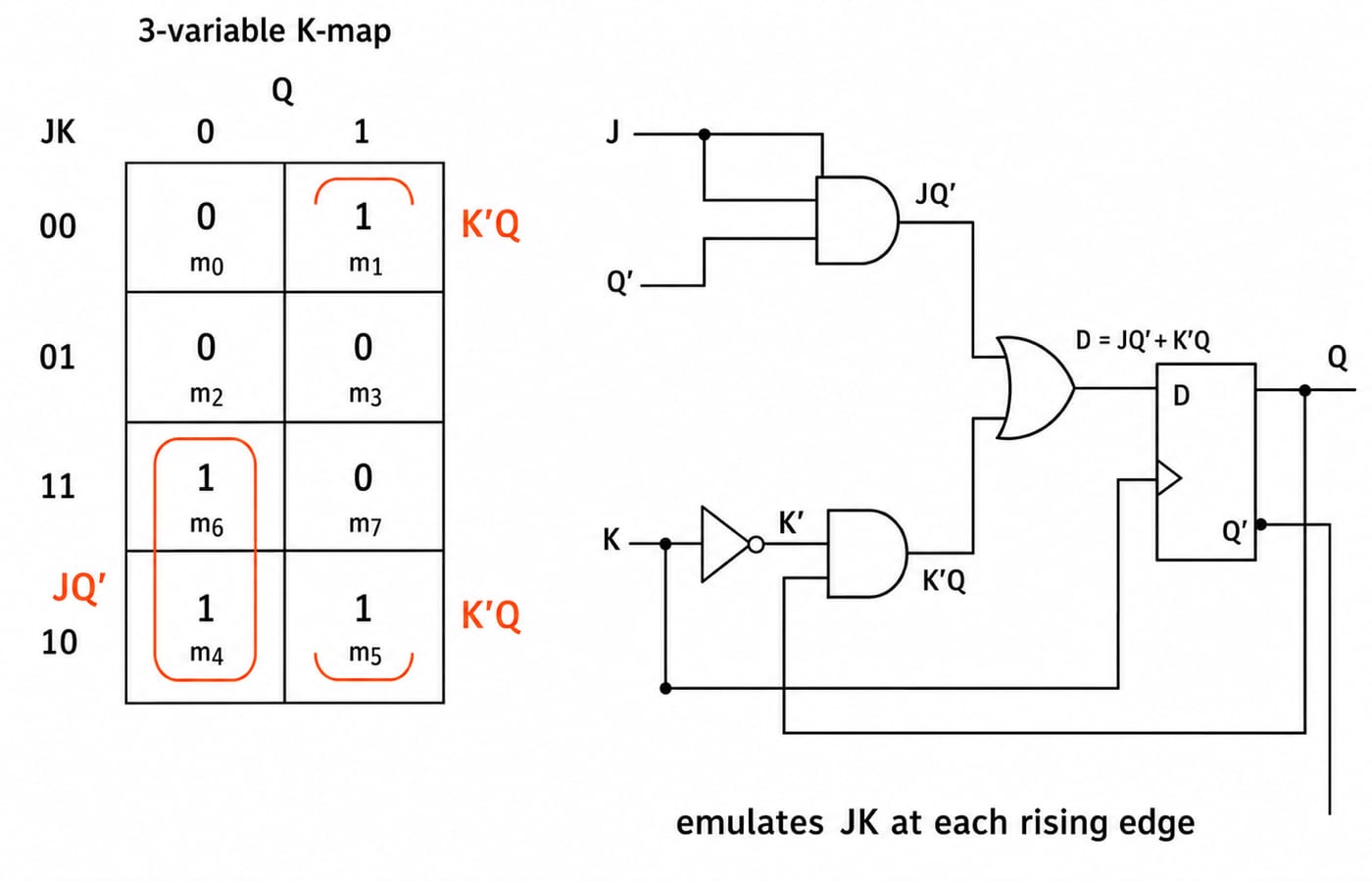
For variable order J,K,Q, the 1-cells are D(J,K,Q)=Sigma m(1,4,5,6). Put the K-map rows in Gray order JK=00,01,11,10, with columns Q=0,1:
|
|
|
|---|---|---|
| 0 | 1 |
| 0 | 0 |
| 1 | 0 |
| 1 | 1 |
Group m4,m6 at Q=0 across JK=10,11 to get JQ'. Group m1,m5 at Q=1 across the top-bottom adjacency JK=00,10 to get K'Q.
Therefore:
D=JQ'+K'Q
This is the JK characteristic equation connected to D.
5. Verify the conversion across six clock edges, not by algebra alone
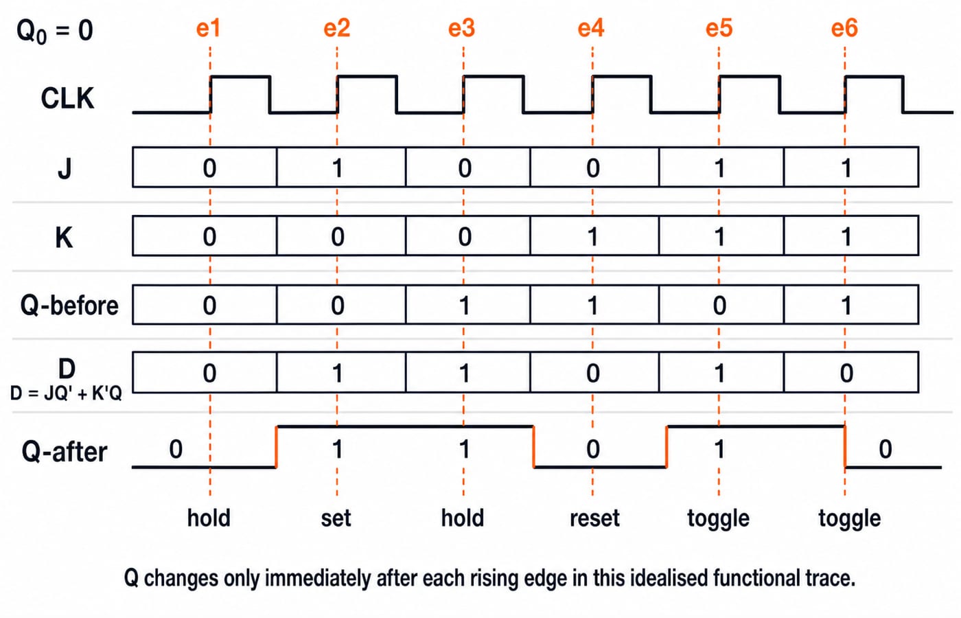
Start with Q0=0 and apply JK=00,10,00,01,11,11 at six rising edges:
edge |
|
|
|
|
| action |
|---|---|---|---|---|---|---|
1 | 0 | 0 | 0 | 0 | 0 | hold |
2 | 0 | 1 | 0 | 1 | 1 | set |
3 | 1 | 0 | 0 | 1 | 1 | hold |
4 | 1 | 0 | 1 | 0 | 0 | reset |
5 | 0 | 1 | 1 | 1 | 1 | toggle |
6 | 1 | 1 | 1 | 0 | 0 | toggle |
Edge 3 gives D=0(0)+1(1)=1; edge 4 gives D=0(0)+0(1)=0. The final rows show why feedback matters. At J=K=1, D=Q', so consecutive edges alternate state. Constant D=1 would set repeatedly, not toggle.
6. Useful conversion shortcuts and why they work
Use these as algebraic cross-checks, not as substitutes for understanding direction:
JK hardware emulating D: choose
J=D, K=D'. ThenQ+=DQ'+DQ=D(Q'+Q)=D.JK hardware emulating T: choose
J=T, K=T. ThenQ+=TQ'+T'Q=T XOR Q.D hardware emulating T: choose
D=T XOR Q. Since D hardware hasQ+=D, it givesQ+=T XOR Q.
These solve opposite problems. D=JQ'+K'Q makes D hardware emulate JK; J=D, K=D' makes JK hardware emulate D. Never detach a shortcut from its direction.
7. Flip-flop conversion traps and representative exam question forms
Tempting move | Why it fails | Correct replacement |
|---|---|---|
Swap desired and available types | It changes which variables are inputs and outputs | Write desired and available before building the table |
Use only a characteristic table when excitation is needed | It does not tell you the required available inputs | Translate each required transition with the available type's excitation rule |
Treat | They describe opposite sides of the active edge | Keep present and next state separate |
Put K-map rows in binary order |
| Use Gray order |
Ignore wrap-around adjacency | You miss valid larger groups | Treat first and last rows or columns as adjacent |
Force SR | That input is invalid | Respect the valid-input restriction |
Forget preset or clear | They can override the clocked path | Analyse asynchronous controls separately |
Representative questions ask for an excitation entry, K-map derivation, wrong-circuit diagnosis, short trace, or minimisation with legal don't-cares. Check against D=Sigma m(1,4,5,6)=JQ'+K'Q; consecutive JK=11 edges from Q=0 produce 1, then 0.
For broader study, use CS Fundamentals for Exams & Placements. Follow it with Sequential Circuits MCQs: Solved Flip-Flops and Counters for solved-question practice, then use GATE Test Series: Mocks & Topic-wise Tests when you are ready to practise under time pressure.
8. Flip-flop conversion: the short version and next step
Fix the conversion direction.
Generate the desired
Q+.Translate each transition into the available inputs.
Minimise using only valid don't-cares.
Verify the complete table and a clock-edge trace.
Now reproduce the result without looking. Write all eight J,K,Q rows, mark m1,m4,m5,m6, recover JQ' and K'Q, then test two toggle edges from Q=0. For a sequenced Digital Logic path around this topic, continue with GATE Guidance by Sanchit Sir. If conversion alone is weak, redo the eight-row table before moving to counters.
Keep learning
Base Conversion Explained: Binary, Octal, Decimal and Hexadecimal Worked Examples
Learn one reliable workflow for converting integers and fractions across bases, with checked examples, shortcut rules and quick questions for practice.
Updated 26 Oct 20267 min readDigital Logic
NOT, OR and AND Gates: Evolution, Truth Tables and a Worked Circuit
Learn how NOT, OR and AND gates developed from switching ideas, then trace F=(A+B')C node by node and confirm it with a complete truth table.
Updated 23 Oct 20265 min readDigital Logic
Binary Arithmetic Operations Explained: Rules and Worked Examples
Learn binary addition, subtraction, multiplication and division with aligned worked examples, then separate carry, borrow and two's-complement overflow.
Updated 19 Oct 20266 min readDigital Logic
1's Complement Explained: Binary Conversion, Addition and Worked Examples
Learn how fixed-width 1's complement numbers represent negatives, why zero has two encodings, and how end-around carry works through exact examples.
Updated 15 Oct 20266 min readDigital Logic