Input and Output Devices in COA: Interfaces, Interrupts and DMA with a Worked Example
Input and output devices in COA explained through interfaces, polling, interrupts and DMA, plus a FIFO that fills in 640 microseconds and loses 6 bytes at 700 microseconds.
KnowledgeGate Team
Exam prep & CS education
Updated 5 Sep 20267 min read
Naming a keyboard as an input device is easy. COA questions go deeper: what sits between the peripheral and the CPU, who moves each unit of data, and how much processor time does the transfer consume? At the device boundary, direction, natural transfer unit and rate behaviour determine why buffering and control are needed. Under the worked assumptions here, a 64-byte FIFO fills in 640 microseconds and loses 6 bytes when the driver arrives 700 microseconds late.
Input and Output Devices: The Peripheral, Controller and CPU Boundary
Input devices send data or events into the computer: keyboard and scanner. Output devices receive data from it: monitor and printer. A touchscreen and network interface are bidirectional. A storage drive is I/O because the computer reads and writes it.
Keep four layers separate. The peripheral acts externally; its controller handles device timing and signalling; the interface exposes a processor-visible contract; driver software uses that contract. This bridges differences in rate, transfer unit, direction and readiness.
Device | Direction | Natural unit | Rate behaviour | Why buffering or control is needed |
|---|---|---|---|---|
Keyboard | Input | Keystroke | Irregular | Preserve events until read |
Block-storage device | Both | Block | Bursty | Bridge block and memory transfers |
Printer | Output | Character or page data | Relatively slow | Prevent CPU waiting and overrun |
Network interface | Both | Frame or packet | Bursty | Absorb arrival and service-rate differences |
I/O Interfaces: Data, Status and Control Registers
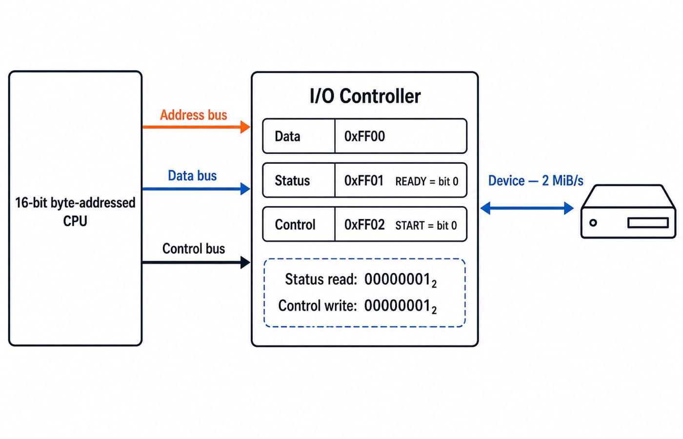
An interface has three register roles. Data holds the transfer unit, status reports ready, busy or error, and control accepts start, reset or interrupt-enable. A handshake issues a command, detects readiness, transfers, and acknowledges completion.
Use this teaching model throughout: an isolated-I/O machine reaches the interface through an 8-bit port space, with DATA at port 0x40, STATUS at port 0x41 and CONTROL at port 0x42, using IN and OUT rather than load and store. STATUS bit 0 is READY and bit 3 is OVERRUN; CONTROL bit 0 is START. Executing OUT 0x42, 00000001 issues start; IN 0x41 returning 00001001 means the device is ready but has already lost data. These port numbers illustrate the mechanism, not a universal hardware map.
For the memory-mapped counterpart traced register by register, with exact bit patterns and a read-to-clear rule, see Computer Interfaces in COA: Registers, Handshaking and I/O Mode Numericals; that post also carries this series' single CPU-occupancy comparison across programmed I/O, interrupts and DMA. This post stays on the device side of the boundary.
With memory-mapped I/O, registers share the memory address space and use ordinary loads and stores. With isolated I/O, they have a separate address space and special instructions. Register selection is separate from selecting instruction operands.
Programmed I/O: Polling Keeps the CPU in the Transfer Loop
For the topic map, three registers, both addressing schemes and interrupt priority in one place, start from Input Output Organisation in COA.
For programmed I/O, software writes START=1 to port 0x42, repeatedly reads port 0x41, tests READY, and then reads or writes data through port 0x40. It repeats until the requested byte count is complete. Repeated status inspection is polling. When the CPU spends its instruction slots only waiting and performing transfer work, it is busy waiting.
Polling is simple, predictable and reasonable for a tiny or very fast operation. A slow or bursty device can instead trap the CPU in the loop. Polling has no fixed cycle cost by itself, so a numerical must provide a poll cost, interval or total busy time. Under programmed I/O, the CPU busy-waits for the whole burst rather than doing other work.
Interrupt-Driven I/O: The Device Signals When Service Is Needed
In interrupt-driven I/O, the controller raises a request. The CPU finishes its current instruction, required state is preserved, and an interrupt service routine identifies and services the device. The request is acknowledged, state is restored, and execution resumes. Interrupt latency, handler service time and interrupt frequency are different quantities.
The CPU can do other work between requests, but entry, service and return all cost time. One interrupt per byte may cost more than one per buffered block, so granularity matters. Interrupting once per filled 64-byte FIFO rather than once per byte cuts entry-and-exit overhead by 64 times for the same payload; granularity, not the interrupt mechanism, is what you tune. This batching is an example assumption, not a property of every device.
DMA: A Controller Moves the Block Between Device and Memory
With direct memory access, the CPU programs the device or source, memory destination, direction and byte count. The DMA controller then arbitrates for the bus and moves the block. A completion interrupt informs the CPU when the work is done. The CPU still initiates and completes the operation, but it does not execute a load/store sequence for every byte.
In burst mode, DMA can hold the bus for a run of transfers. In cycle stealing, it takes selected bus cycles. Larger bursts can improve transfer efficiency but delay CPU memory traffic; cycle stealing spreads that interference over time. Neither is universally best.
DMA setup and completion still cost the CPU real cycles, which is why a controller earns its keep on a full block and loses on a single byte. DMA is not zero-overhead and does not guarantee lower wall-clock time merely because CPU involvement is lower.
Worked Example: Size the Controller FIFO So the Device Never Overruns
Fix the device-boundary assumptions first:
Input device production rate: 100,000 bytes per second
Controller FIFO depth: 64 bytes
Driver's worst-case service latency: 700 microseconds
Ignore bus contention
This example measures data loss at the device boundary, not CPU occupancy.
The input device produces 100,000 bytes per second, so the arrival interval is:
1,000,000 microseconds per second / 100,000 bytes per second = 10 microseconds per byte
The controller FIFO holds 64 bytes, so its fill time is:
64 bytes x 10 microseconds per byte = 640 microseconds
The driver's worst-case service latency is 700 microseconds. During that gap:
700 microseconds / 10 microseconds per byte = 70 whole bytes. The convention is that the first byte lands 10 microseconds after the service window opens, so the seventieth byte lands at 700 microseconds.
Only 64 bytes fit in the FIFO, so the loss is:
70 bytes - 64 bytes = 6 bytes lost per late service
The controller sets the STATUS OVERRUN bit because complete arriving bytes had nowhere to go. To be overrun-free, the required FIFO depth is:
700 microseconds / 10 microseconds per byte = 70 bytes
The FIFO must therefore hold at least 70 bytes, so the next practical size is a 128-byte FIFO. These values define this example, not universal hardware.
Buffering is not politeness, it is arithmetic: the FIFO must cover the worst-case gap between device production and driver service.
Input and Output Devices in Exam Questions: Patterns and Traps
Questions can ask you to classify direction, identify a controller or register, trace READY, START and OVERRUN, distinguish memory-mapped from isolated I/O, order interrupt steps, or decide who moves data. A FIFO numerical instead asks how many whole bytes arrive during the worst-case service gap and whether the configured depth can hold them.
Use a fixed order: calculate the arrival interval with units, multiply or divide to find whole-byte arrivals during the latency, compare arrivals with FIFO depth, and report both lost bytes and the minimum safe depth. Keep that device-boundary calculation separate from CPU occupancy.
Tempting shortcut | Why it fails | Correct check |
|---|---|---|
Judge input/output from the human viewpoint | Direction is relative to the computer | Follow data at the computer boundary |
Treat interrupt I/O as DMA | An interrupt handler may still move each unit | Identify who performs the movement |
Assume DMA means no CPU work | Setup and completion still cost cycles | Count both once |
Assume a bigger FIFO always helps | A FIFO only covers the service gap you actually have | Compare FIFO depth against worst-case driver latency |
Assume the FIFO empties instantly | The driver drains only after it arrives | Compare the 640-microsecond fill time against the 700-microsecond latency |
Treat OVERRUN as a driver bug | It is a rate-and-depth mismatch | Recompute 64 x 10 microseconds against the service latency |
Input and Output Devices: The Short Version and Next Step
Programmed I/O keeps the CPU in the loop. Interrupt-driven I/O lets the device request CPU service. DMA lets a controller move the block while the CPU handles setup and completion. In every case, the interface exposes data, status and control rather than leaving the CPU to understand the peripheral's physical details.
For pure rate-and-overhead drill questions, use DMA, Interrupts and Programmed I/O for GATE, which prices stolen bus cycles and ISR fractions rather than buffer depth.
Reproduce the FIFO calculation from blank paper. Then change the driver's worst-case latency to 1,200 microseconds: 1,200 / 10 = 120 bytes arrive, 120 - 64 = 56 are lost, and the FIFO would need at least 120 bytes.
If you want this topic inside a GATE-oriented route, continue with GATE Guidance by Sanchit Sir and the GATE CS Exam Preparation category. For a broader grounding across CS fundamentals, use Zero to Hero, Complete CS Course.
Keep learning
Pipelining Basics in Computer Architecture: Clock Cycle, Speedup and Hazard Worked Examples
Learn how to calculate a pipeline clock, fill and drain time, finite-batch speedup, latency, throughput, and the cost of a load-use stall.
Updated 23 Oct 20266 min readComputer Organization & Architecture
Data Manipulation Micro-Operations in COA: Arithmetic, Logic and Shift Operations Worked Step by Step
Learn a fixed-width method for tracing arithmetic, logic, and shift micro-operations. Every example tracks register values, result bits, carry, and overflow.
Updated 19 Oct 20265 min readComputer Organization & Architecture
Assembly Language and Assembler Design: Two-Pass Translation with a Complete Worked Example
Follow a 16-bit Basic Computer program through pass one, pass two, hexadecimal encoding and execution, with every symbol, address and result shown.
Updated 15 Oct 20266 min readComputer Organization & Architecture
Computer Classification and Flynn’s Taxonomy: The Four Classes with a Worked Vector Example
A machine can belong to several computer classes at once. Learn the four classification axes, Flynn’s matrix, vector and multicore traces, and exam traps.
Updated 11 Oct 20266 min readComputer Organization & Architecture